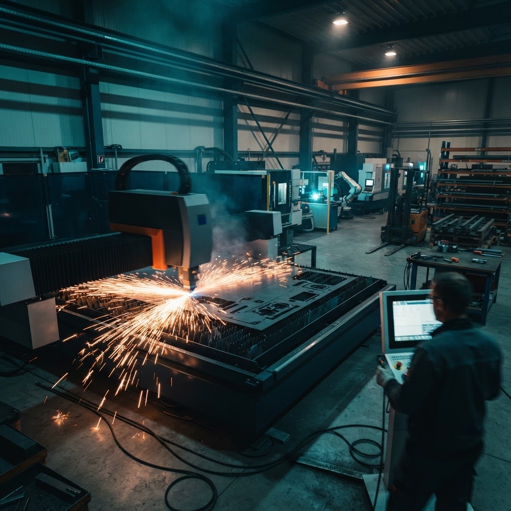
Custom Sheet-Metal Manufacturing
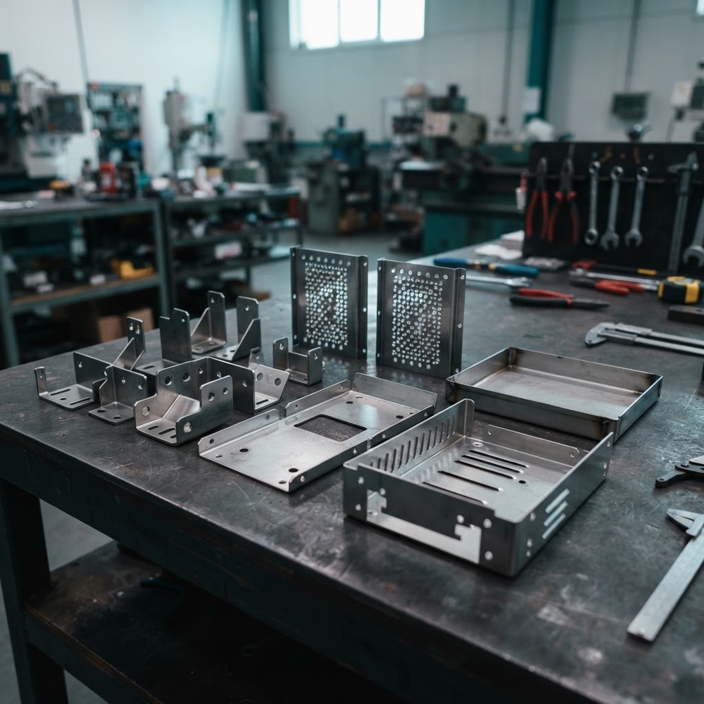
Brackets, trays, panels, housings, and other custom sheet-metal parts.
INDUSTRY SOLUTIONS
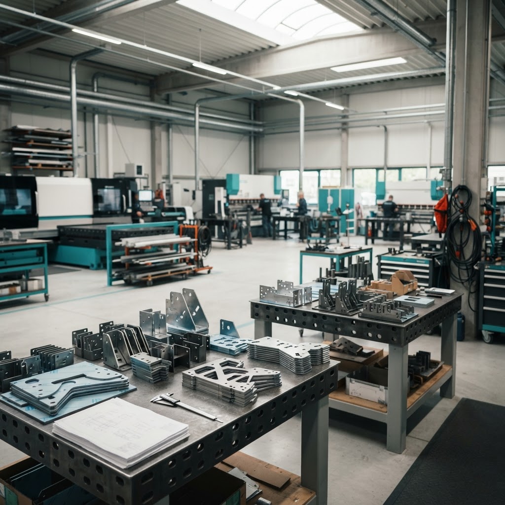
Manufacturing businesses move customer designs through engineering review, estimating, production preparation, manufacturing, and delivery. eSquall helps identify where supported software, design processing, and information flow can improve these connected workflows.
Manufacturing companies work with customer requirements, technical drawings, design files, material specifications, production planning, and quality requirements to produce finished components. Depending on the manufacturing process, teams may need to review drawings, prepare geometry, estimate material and machine costs, and coordinate information across multiple applications.
Different manufacturing businesses have different operational needs. Understanding the company’s actual process is the first step toward identifying suitable software opportunities.
Information typically moves between these activities before a component is produced.
Our initial manufacturing focus is businesses that make custom metal components from customer-provided designs.
Brackets, trays, panels, housings, and other custom sheet-metal parts.
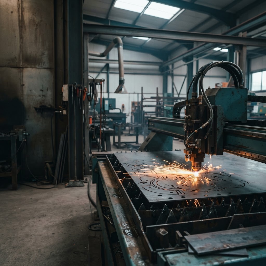
Cutting metal sheets from suitable 2D outlines and material specifications.
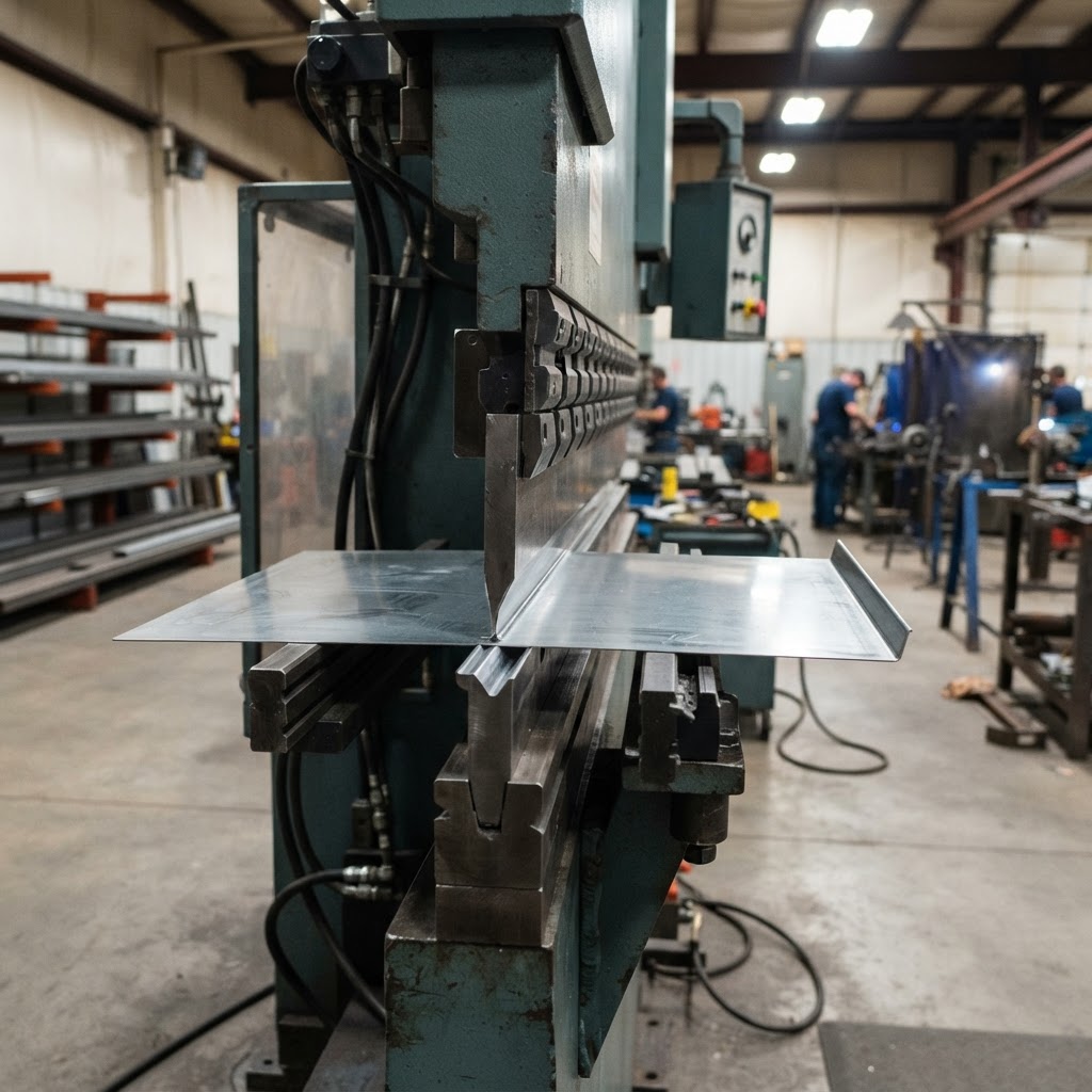
Cutting and bending workflows that may require suitable 3D models to be unfolded.
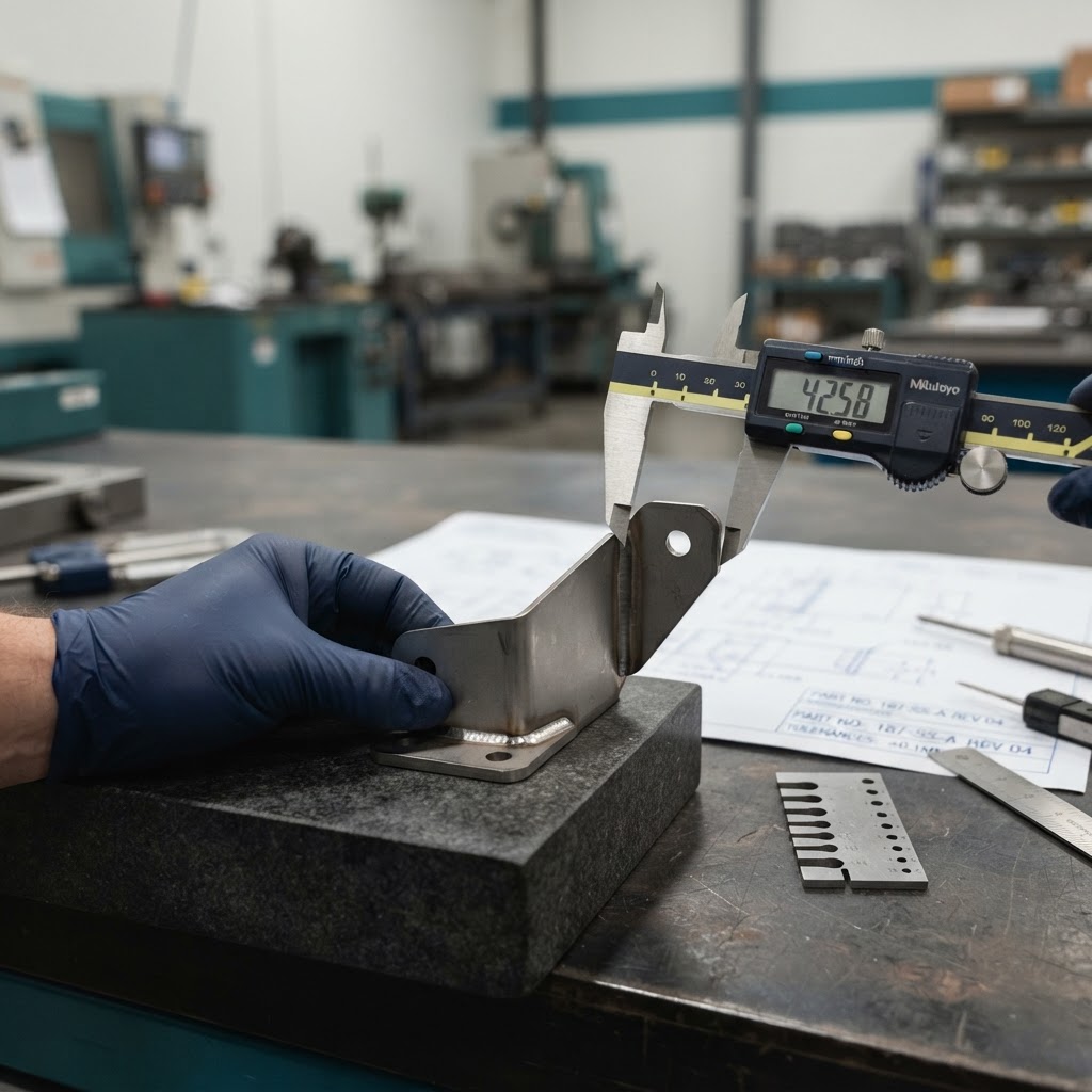
Detailed specifications, tolerances, revisions, and careful quotation requirements.
These are target industry segments identified by the research, not confirmed eSquall customers. Wood, glass, tube cutting, and general machining are treated as potential future research because their manufacturing requirements differ.
Specialized Focus
For custom sheet-metal, laser-cutting, and press-brake shops, eSquall assesses CAD-to-quote, nesting, and job-tracking workflows. This focused solution helps connect supported part files, shop-specific estimating inputs, and accepted work through production.
A general view of how information moves between design submission, engineering review, and quotation preparation in a manufacturing business.
This workflow represents a general manufacturing process based on the research. Actual workflows differ between companies.
Operational considerations identified in the research. Not every manufacturer experiences all of them, and no statistics or loss figures are implied.
Manufacturers receive design files from different CAD applications. File format, geometry, units, and the intended manufacturing process determine how a file can be used.
Dimensions, tolerances, drawing revisions, and manufacturing assumptions need appropriate review before information is used for production or quotation.
Estimators may need to combine design information with material rates, machine rates, quantities, and required operations to prepare a quotation.
Manufacturing businesses may use separate CAD, nesting, CAM, estimating, ERP, accounting, and CRM applications. Repeated manual data transfer may create opportunities to evaluate software integration.
These are the general industry roles of common design formats. They are explained separately from the formats actually supported by eSquall’s implementation, which should be confirmed against representative test files.
Drawing geometry such as lines, arcs, circles, and outlines may be used to prepare suitable two-dimensional cutting profiles.
CAD drawings may contain two-dimensional or three-dimensional geometry, annotations, and multiple views. The relevant geometry and units must be interpreted correctly.
Three-dimensional geometry exchange formats that can transfer models between CAD applications. Suitable sheet-metal models may require further preparation before unfolding.
SOLIDWORKS part files that may require a compatible import and sheet-metal preparation workflow.
Autodesk Inventor part files relevant to the processing workflow described in the research, subject to file compatibility and verification.
Other formats mentioned in the industry research, such as IGES, X_T, X_B, SAT, PRT, SVG, AI, EPS, PDF, 3DM, and F3D, are relevant to ongoing research. They are not presented here as existing supported capabilities, and complete automatic interpretation of scanned PDF drawings is not claimed.
An important manufacturing concept, from 3D geometry to nested flat parts.
A three-dimensional model represents the intended component geometry.
For suitable sheet-metal models, unfolding produces a flat pattern that can support cutting preparation and estimating.
Nesting arranges prepared flat parts on a sheet to help plan material use and reduce avoidable waste.
Flat-pattern preparation and nesting are different stages. Nesting requires suitable prepared flat geometry, and not every 3D model can be unfolded automatically.
Manufacturers may use different applications for different purposes. These are examples of software used in the industry, not confirmed eSquall integrations.
Used to create technical drawings and 3D part models.
Examples in the research: AutoCAD, SOLIDWORKS, Autodesk Inventor, Autodesk Fusion
Used to arrange prepared flat parts on sheets.
Examples in the research: SigmaNEST, TruTops Boost
Used to prepare manufacturing instructions for supported production equipment.
Examples in the research: ProNest, Lantek, and relevant Autodesk manufacturing tools
Used to calculate job costs and prepare customer quotations.
Examples in the research: SigmaQUOTE, Paperless Parts, SecturaFAB
Used to coordinate business operations such as orders, inventory, purchasing, and production.
Examples in the research: ECI M1, JobBOSS², Global Shop Solutions
Used to manage customer relationships and financial records.
Examples in the research: Salesforce, HubSpot, QuickBooks, Xero
When information must be transferred repeatedly between systems, a suitable custom software solution or integration may be worth evaluating. The appropriate approach depends on the applications involved, available interfaces, data ownership, and validation requirements.
Areas identified in the research where supported software, design processing, or integration may help manufacturing workflows.
Supported file-processing workflows may help extract or prepare relevant geometry and measurements for further review. Universal CAD compatibility and complete automatic engineering review are not implied.
Suitable sheet-metal models may need flat-pattern preparation before nesting and material planning. Processing and nesting depend on appropriate input geometry and require validation.
Repeated manual transfer between CAD, estimating, ERP, and other systems may indicate an opportunity to assess integration or custom software. Scope should be defined after reviewing requirements and technical environment.
eSquall does not claim to already integrate with every CAD, CAM, ERP, CRM, or estimating application listed on this page.
How a manufacturing software opportunity is evaluated before any scope is confirmed.
Step 1
Review the current workflow, file formats, required outputs, existing software, and operational requirements.
Step 2
Evaluate representative files, compatibility, geometry, validation needs, integration possibilities, and technical limitations.
Step 3
Identify the appropriate solution scope, implementation requirements, and measurable criteria for evaluating success.
Potential benefits and ROI must be measured using actual project costs and before-and-after results. No unverified ROI figures or savings claims are published.
Discuss Your Workflow
Every manufacturing business has its own processes, design requirements, and software environment. Tell us how your team handles design files, engineering review, quotation preparation, and information transfer between systems so we can discuss the relevant technical requirements.
We use cookies to enhance your browsing experience, serve personalized content, and analyze our traffic. We also use Zoho PageSense cookies to analyze visitor behavior and improve site experience. By clicking "Accept All", you consent to our use of cookies. You can customize your preferences anytime.