CAD File Processing
Assess supported design files and the information that may be extracted from suitable files, with results validated against representative examples.
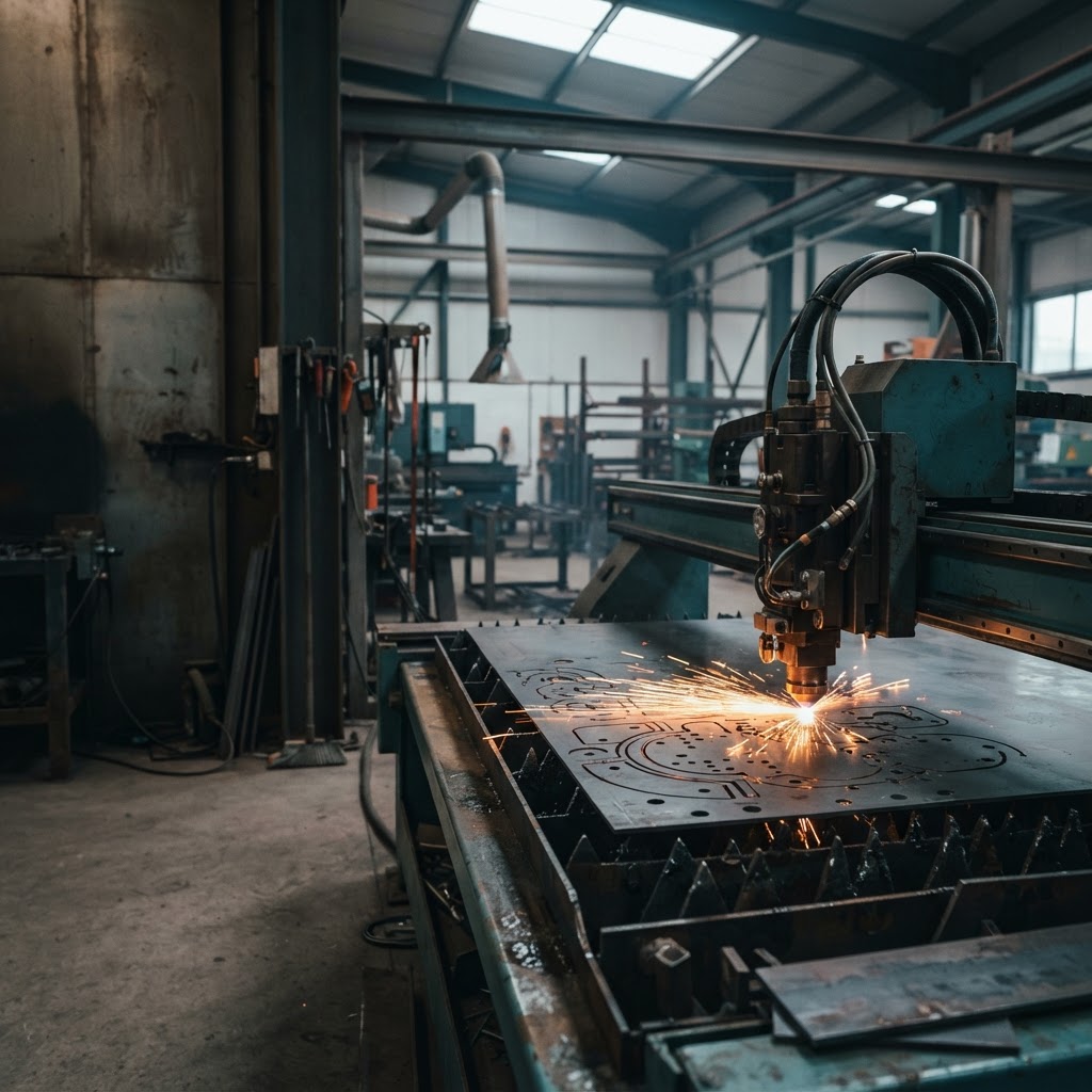
Manufacturing Software
eSquall helps custom manufacturers assess and build software for the work between receiving a customer design and preparing a quotation. We review your workflow, representative design files, existing systems, and information handoffs to define where supported CAD processing, design preparation, or system integration may help.
Why Manufacturers Work With eSquall
When drawings, job details, measurements, and pricing information move between teams or systems, staff may need to re-check files, re-enter data, or clarify missing details. eSquall assesses these handoffs and helps define software that supports the workflow your team already uses.
What we can help with
Start with the part of your workflow that creates the most repeat work. We assess the systems, information, and review steps involved before recommending a scope.
Assess supported design files and the information that may be extracted from suitable files, with results validated against representative examples.
Evaluate flat-pattern preparation for suitable sheet-metal models and the transfer of prepared flat geometry into downstream workflows.
Help make reviewed job information available to estimating teams, reducing repeated entry where systems and processes support it.
Review the software, interfaces, permissions, and data flows involved before recommending an integration.
These are areas to assess and scope. The final solution depends on representative files, existing software, pricing rules, and validation requirements.
Who We Support
Our initial manufacturing focus is custom sheet-metal businesses that receive customer designs and prepare parts for quoting and production.
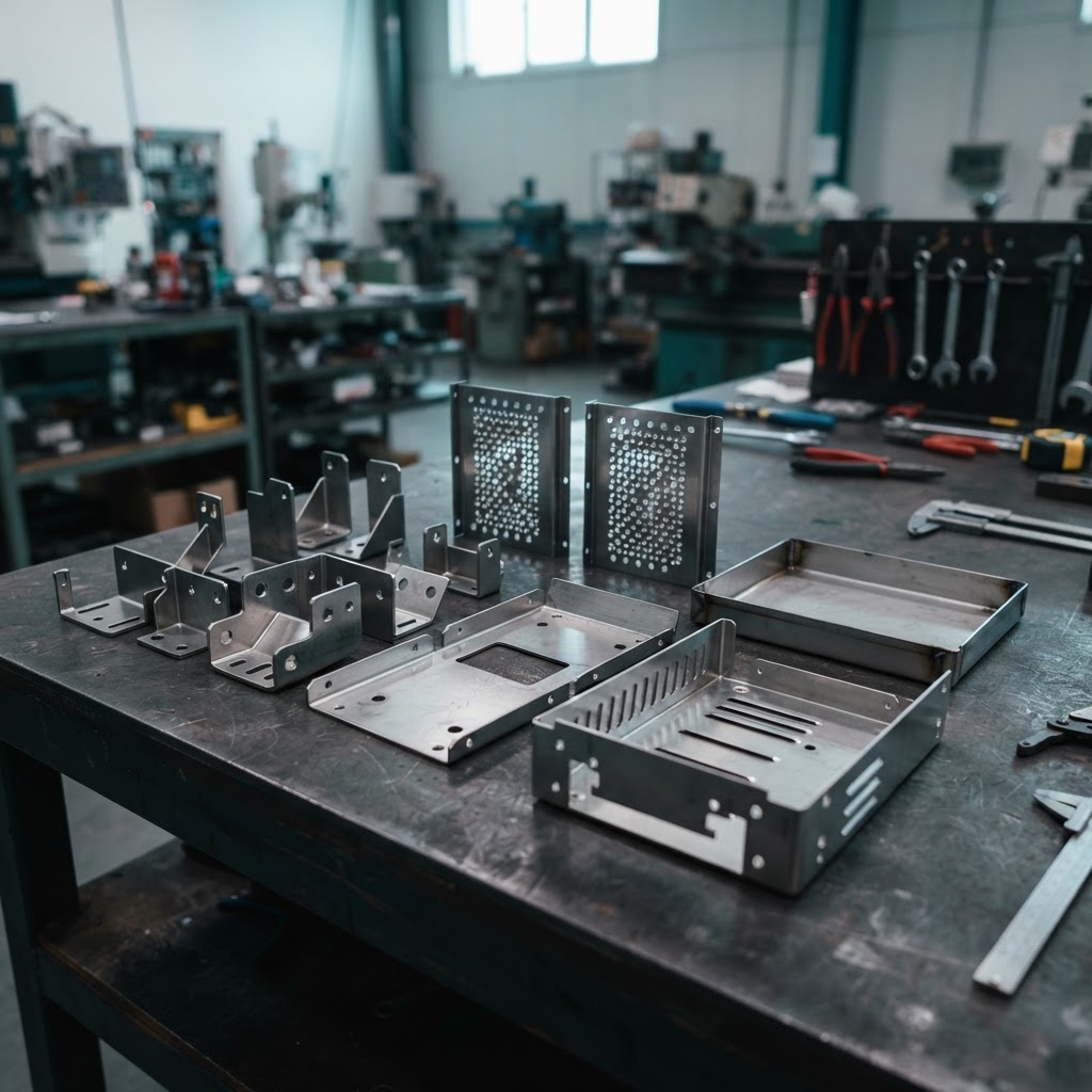
Custom brackets, trays, panels, and housings that need drawing review, dimension checks, material estimates, and quotations.
Laser-cutting workflows depend on usable 2D cutting outlines, correct dimensions, material specifications, and suitable production preparation.
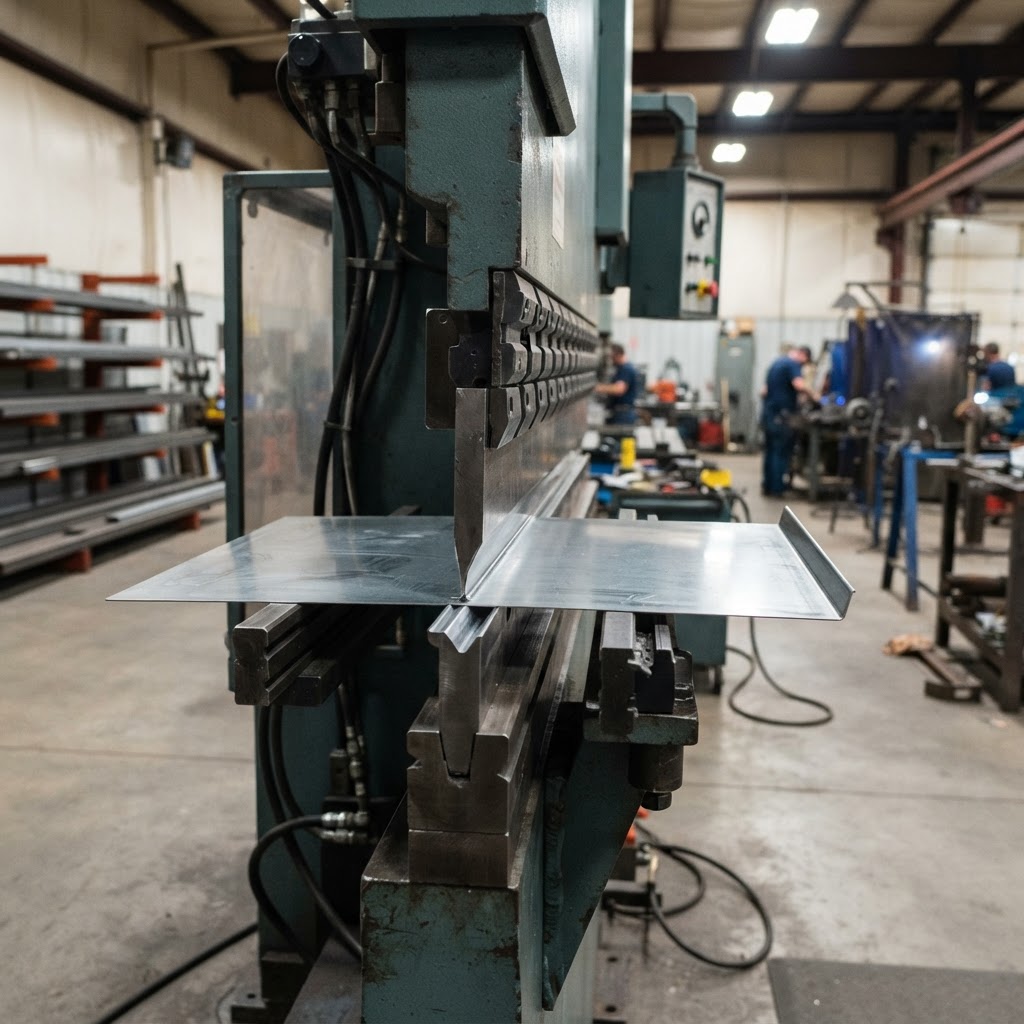
Cutting and bending work may need suitable 3D sheet-metal models unfolded into flat patterns before cutting and estimating.
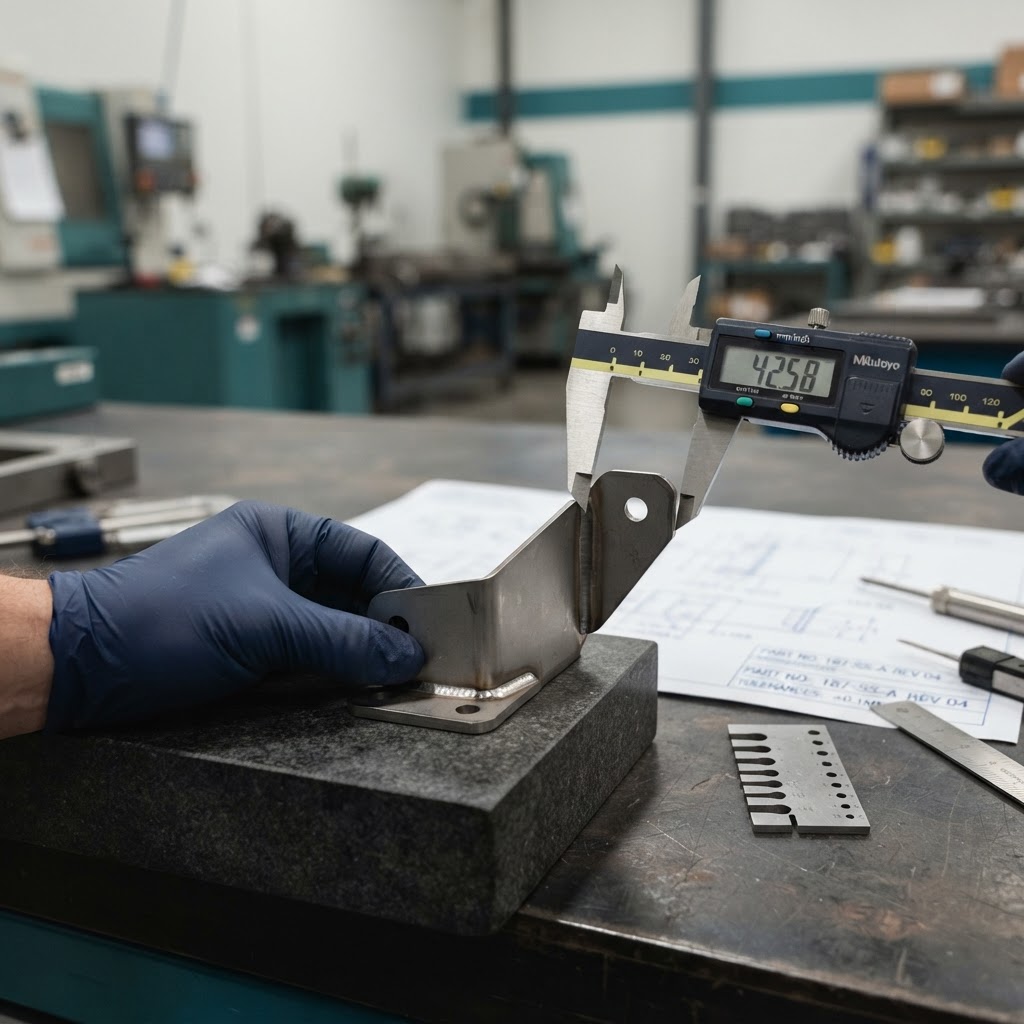
Precision fabrication involves detailed specifications, tolerances, drawing revisions, and quotation requirements that must be reviewed carefully.
How the Workflow Works
A typical enquiry moves through several teams before it becomes a quotation and production job. eSquall focuses on the information handoffs within this workflow.
01
Customers submit design files and job requirements, potentially including material, thickness, quantity, required operations, quality specifications, and delivery expectations.
02
The manufacturer checks whether submitted files open correctly and whether the information required for estimating is complete.
03
The relevant team checks geometry, units, drawing revisions, dimensions, and manufacturing suitability.
04
Reviewed design information is combined with approved material costs, machine rates, and operation rates to prepare a quotation.
05
After quotation acceptance, the manufacturer plans materials, production capacity, and the instructions needed for manufacturing.
06
Finished parts are inspected, delivered, and processed through the relevant delivery and invoicing workflows.
Clearer information at each handoff can help teams review the right file, revision, and job details before moving to the next step.
Design Files and Processing Scope
We assess the file formats, geometry, units, and processing routes involved in your workflow. File support is confirmed through representative sample files and agreed expected outputs, not by file extension alone.
File Formats We Assess
DXF files can contain lines, arcs, circles, and polylines that may be used to prepare suitable cutting outlines and extract measurements.
DWG files may contain two-dimensional or three-dimensional geometry, notes, and multiple views. The relevant part and units must be interpreted correctly.
STEP files allow three-dimensional geometry to be transferred between CAD applications. Suitable sheet-metal models may require additional preparation before unfolding.
Suitable part models may be processed through an import and sheet-metal preparation workflow, subject to compatibility and validation.
Inventor part files are relevant to the existing reported processing workflow. Actual compatibility depends on the file and supported processing route.
Conceptual illustrations, not eSquall product screenshots or verified processing outputs.
Sheet-Metal Design Preparation
For suitable sheet-metal models, we assess whether a 3D design can be prepared as a flat pattern and whether the resulting flat geometry can be used in a nesting workflow.
Stage 1
The model represents the finished component and its geometry.
Stage 2
A suitable model can be unfolded into a flat pattern for cutting preparation and estimating.
Stage 3
Nesting arranges prepared flat parts on a sheet. The resulting layout can be reviewed as part of material planning; results depend on the parts, sheet specifications, and nesting rules.
Illustrative sequence only. Unfolding suitability and bend assumptions require validation; nesting uses prepared flat geometry, not raw STEP files. No material-saving or accuracy guarantee is implied.
Existing Systems and Integrations
Your workflow may involve separate CAD, nesting, CAM, estimating, ERP, CRM, and accounting systems. We assess which systems hold the source of truth, what information needs to move, and whether a suitable integration path exists.
AutoCAD, SOLIDWORKS, Autodesk Inventor, Autodesk Fusion
SigmaNEST, TruTops Boost
ProNest, Lantek, Autodesk Fusion and other relevant manufacturing tools
SigmaQUOTE, Paperless Parts, SecturaFAB
ECI M1, JobBOSS², Global Shop Solutions
Salesforce, HubSpot, QuickBooks, Xero
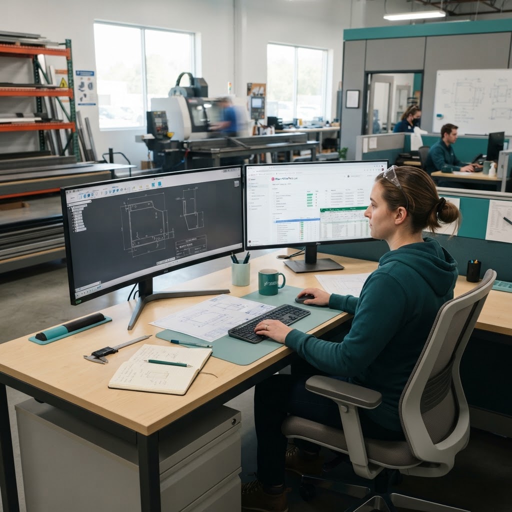
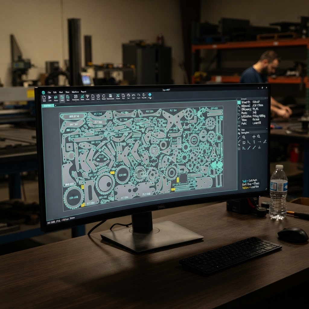
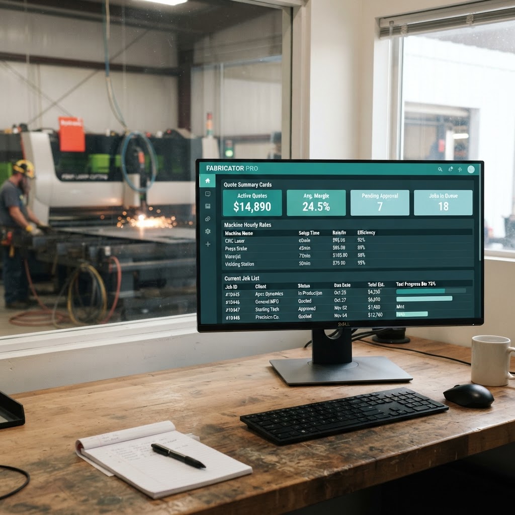
Software examples from the assessment, not confirmed eSquall integrations or endorsements.
When employees repeatedly transfer the same information between systems, a custom software solution or integration may be worth evaluating. The appropriate approach depends on the client's existing applications, available interfaces, data ownership, and validation requirements.
How We Work With You
Review how design files are received, checked, quoted, and prepared for production.
Assess representative files, required outputs, existing software, and integration options.
Agree on the software, processing, integration, and validation work required before development begins.
What we are working on
Our manufacturing work includes an ongoing design-to-quotation workflow project involving supported CAD file processing, selected part-information extraction, flat-pattern preparation for suitable sheet-metal models, and nesting of prepared flat geometry. Project scope, file support, and outcomes are validated against representative files and client requirements.
Manufacturing Software FAQs
Start With Your Current Workflow
Tell us how your team receives design files, reviews job details, prepares quotations, and moves information between systems. We can assess your workflow and discuss what may need to be validated before a solution is scoped.
We use cookies to enhance your browsing experience, serve personalized content, and analyze our traffic. We also use Zoho PageSense cookies to analyze visitor behavior and improve site experience. By clicking "Accept All", you consent to our use of cookies. You can customize your preferences anytime.